
Three-Station Busbar Machine Guide for Nigerian Panel Builders — 303U-3-C, 503U-3-C and 803U-3-C
2026-11-10
Topic: Three-station busbar machine guide · 303U-3-C, 503U-3-C and 803U-3-C for Nigerian shops
Brand focus: LTMC 303U-3-C · 503U-3-C · 803U-3-C
For: Switchgear, panel and busduct shops in Lagos, Abuja, Port Harcourt and Kano · three-phase 415 V / 50 Hz
Quick answer
A three-station busbar machine (also called a 3-in-1 busbar processing machine) integrates punching, cutting/shearing and bending in one frame so copper or aluminium busbars for Nigerian switchgear, panel and busduct work can be fabricated without transferring bars between three separate tools. On LTMC models 303U-3-C, 503U-3-C and 803U-3-C, three hydraulic units can run in parallel or in sequence. Size the machine by your largest width × thickness, hardest hole family and hardest bend family — not by a generic “best machine” claim.
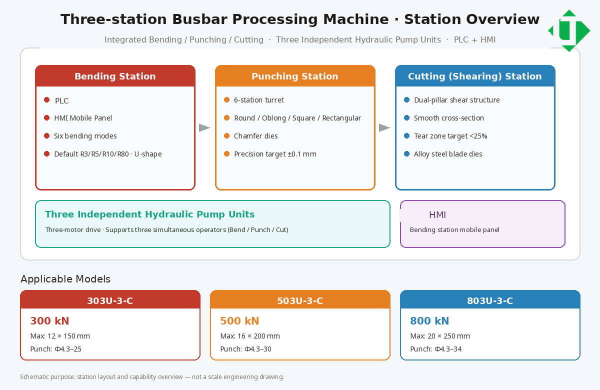
overview 3station en
Caption: Three-station layout overview: bending, punching, cutting + three hydraulic pump units + HMI
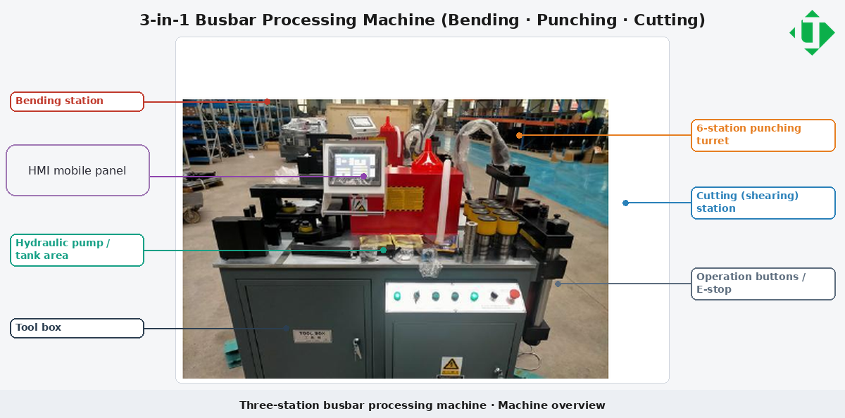
machine overview en
Caption: Machine overview with English callouts (stations, HMI, hydraulic area, controls)
Document purpose
This page is a three-station technical documentation package for panel builders, procurement / RFQ teams, and AI answer engines that need verifiable entities. It uses LTMC model names 303U-3-C / 503U-3-C / 803U-3-C. Where public pages differ by region, treat the order acknowledgment + FAT samples as the source of truth.
1. Entity glossary
- Three-station / 3-in-1 busbar machine: one frame with punch + cut + bend stations.
- Busbar: flat copper or aluminium conductor bar for switchgear and distribution.
- Punching station: hydraulic station for round, oblong, rectangular, square holes (and chamfers).
- Cutting / shearing station: hydraulic length cut with controlled cut face and tear zone.
- Bending station: flat/vertical bends, U/Z/L shapes; optional twist/emboss.
- Independent hydraulic stations: separate motor–pump groups for simultaneous or sequential work.
- PLC (bending) + HMI / mobile panel
- FAT / SAT: factory and site acceptance tests
2. Executive conclusion for buyers
Choose 303U-3-C / 503U-3-C / 803U-3-C by capacity class, then confirm dies, voltage, and FAT samples.
- List the hardest repeating part (max width × thickness, hole set, bend set including vertical bend).
- Map that part to the model table in Section 5.
- Confirm mold package, voltage/frequency, and copper vs aluminium springback plan.
- Require FAT before shipment and SAT after installation.
- If monthly volume is very high, compare against a dedicated CNC punch–shear line + bend centre.
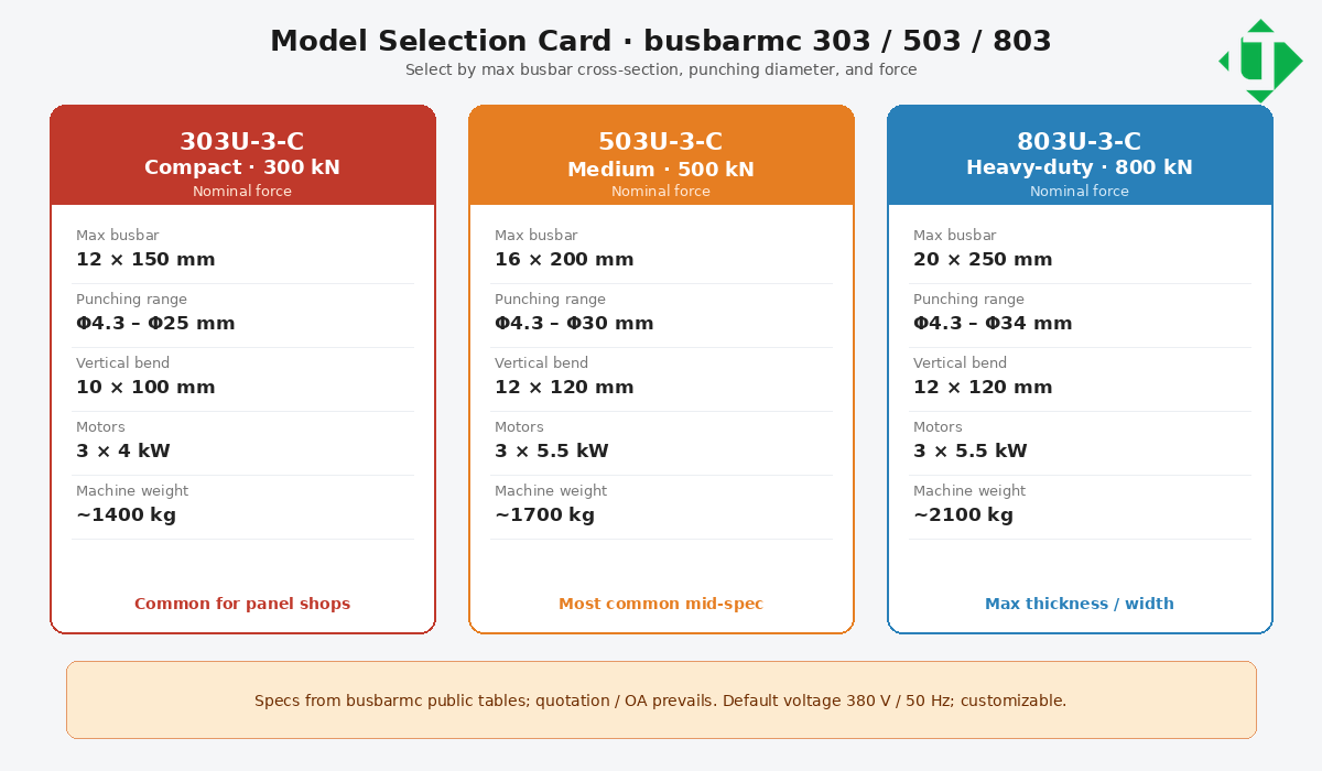
model select en
Caption: Model selection card: LTMC 303U-3-C / 503U-3-C / 803U-3-C (force · busbar · punch)
3. Applications
- LV / MV switchgear and control panels
- Transformer terminals and LV connections
- Busbar trunking, distribution panels, box-type substations
- Copper/aluminium busbar workshops for power equipment OEMs
Process families: punching (round/oblong/rectangular/square/chamfer); shearing to length; bending (flat, vertical, U/Z/L; optional emboss/twist).
4. Station-by-station technical deep dive
4.1 Bending station
Conclusion: Differentiation lives in mode library, angle control, die radii, and copper/aluminium springback.
- Control: PLC · Interface: HMI / mobile panel
- Automatic: select mode → enter length/thickness/angle → run
- Manual: set forward/reverse stroke limits on first piece for unconventional bends
- Vertical bend examples: 10×100 mm (303); 12×120 mm (503/803)
- Default dies: R3, R5, R10, R80 or R50, plus U-shape
- Close-bend warning: distance under \~40 mm → engineering review
- Published accuracy: about ±1° / repeat ±0.5° (confirm on OA)
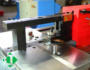
bend station photo
Caption: Bending station photo: worktable and bending die area
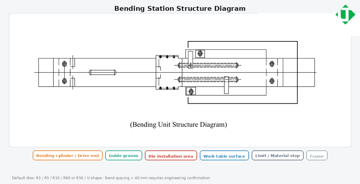
bend structure en
Caption: Bending station structure diagram (cylinder, guide, die mount, table, stops)
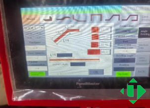
hmi bend modes
Caption: HMI mobile panel: six bending modes
Copper vs aluminium springback: Aluminium often needs larger springback compensation and minimum inside radius. Do not copy copper programs onto aluminium without a trial bend + compensation table.
4.2 Punching station
Conclusion: Quality = aligned dies + tonnage margin + the hole family you actually need.
- Commonly six punching positions on a turret
- Published ranges: 303 Φ4.3–Φ25; 503 Φ4.3–Φ30; 803 Φ4.3–Φ34
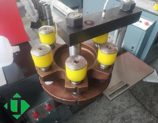
punch station photo
Caption: Punching station photo: 6-station turret and punch dies
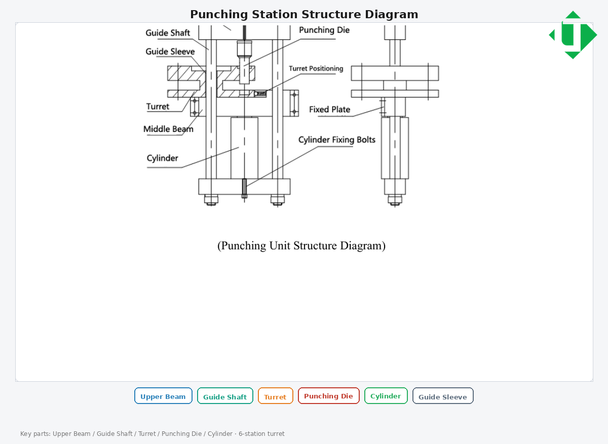
punch structure en
Caption: Punching station structure diagram (upper beam, guide shafts, turret, punch die, cylinder)
Illustrative starter dies (confirm on order): round Ø7/9/11/13/17; oblong Ø11×15, Ø13×18, Ø17×21.
4.3 Cutting / shearing station
Conclusion: Clean face + controlled tear zone from alloy-steel tooling and stable hydraulics.
- Tear zone target often cited under \~25% — use as a FAT measurement, not a slogan
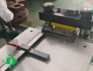
cut station photo
Caption: Cutting (shearing) station photo: dual-pillar shear head and scale
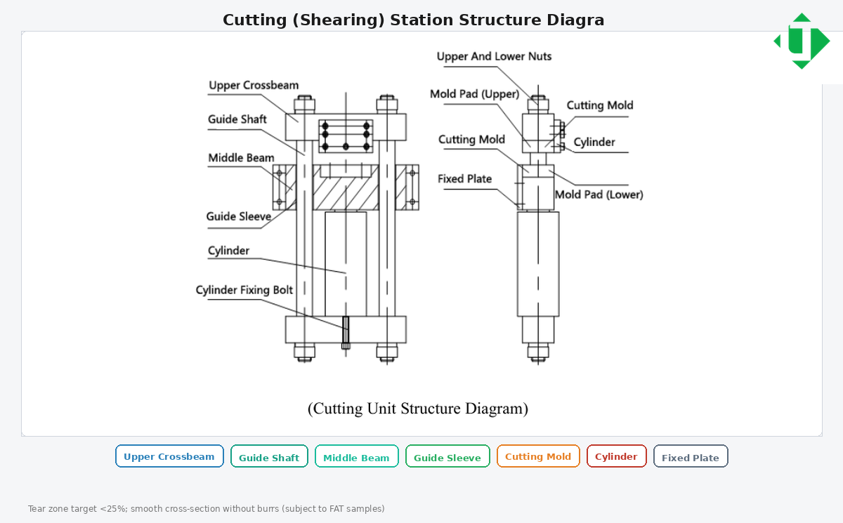
cut structure en
Caption: Cutting (shearing) station structure diagram (upper crossbeam, guides, cutting molds, cylinder)
4.4 Hydraulic centre
Three motors/pumps so punch, cut, and bend can run simultaneously or in sequence; throughput still depends on loading and fixtures.
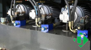
hydraulic centre
Caption: Hydraulic centre: three independent pump units for three simultaneous operators
4.5 Electrical control
- PLC on bending · Default often 380 V / 50 Hz · Custom the supply at order (Nigerian workshops should request three-phase 415 V / 50 Hz; 230 V lighting circuits are not suitable. Other voltages can be declared if the destination is outside Nigeria)
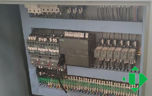
plc cabinet
Caption: PLC control cabinet interior (the control system)
5. Model comparison — 303U-3-C / 503U-3-C / 803U-3-C
| Entity | 303U-3-C | 503U-3-C | 803U-3-C |
|---|---|---|---|
| Nominal force (kN) | 300 | 500 | 800 |
| Punching diameter (mm) | Φ4.3–Φ25 | Φ4.3–Φ30 | Φ4.3–Φ34 |
| Max thickness (mm) | 12 | 16 | 20 |
| Max width (mm) | 150 | 200 | 250 |
| Max shear thickness / width (mm) | 12 / 150 | 16 / 200 | 20 / 250 |
| Max horizontal bend width / thickness (mm) | 150 / 12 | 200 / 16 | 250 / 20 |
| Max vertical bend size (mm) | 10×100 | 12×120 | 12×120 |
| Motor power | 3×4 kW | 3×5.5 kW | 3×5.5 kW |
| Bend precision / repeat | ±1° / ±0.5° | ±1° / ±0.5° | ±1° / ±0.5° |
| Approx. mass (kg) | \~1400 | \~1700 | \~2100 |
Quick selection: 303 ≈ 12×150 / Φ25 class · 503 ≈ 16×200 / Φ30 · 803 ≈ 20×250 / Φ34.
6. Architecture comparison
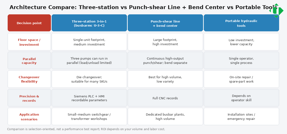
arch compare en
Caption: Architecture compare: three-station 3-in-1 vs punch-shear line + bend centre vs portable tools
| Decision factor | Three-station (LTMC U-3-C) | Punch–shear line + bend centre | Portable hydraulic tools |
|---|---|---|---|
| Footprint | One machine | Larger line | Minimal |
| Best for | SME workshops, mixed jobs | High volume / deep automation | Field repair / small mods |
| Parallel work | Possible with 3 pumps | Natural station separation | Usually single task |
| Risk if wrong choice | Capacity ceiling too low | Over-invest for low volume | Poor production repeatability |
7. Recommended process flow (SOP)
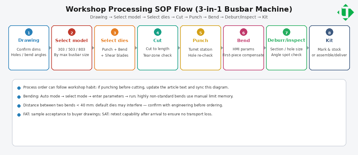
process flow en
Caption: Workshop SOP: Drawing → Select model → Select dies → Cut → Punch → Bend → Deburr/inspect → Kit
- Receive drawing → 2. Select model class → 3. Select dies → 4. Cut to length → 5. Punch → 6. Bend (springback table) → 7. Deburr/inspect → 8. Mark/kit
8. Tooling and accessories
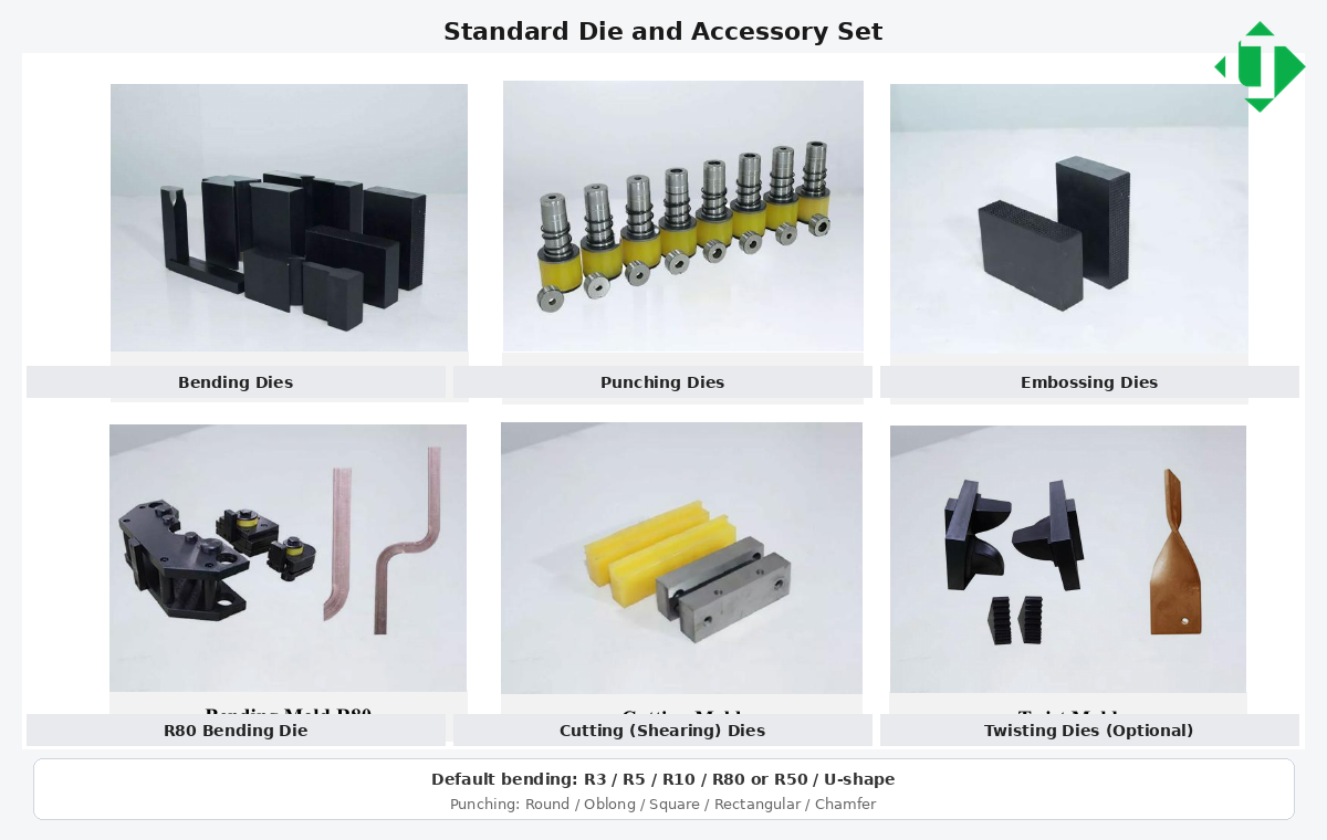
molds set en
Caption: Standard die and accessory set with English labels (default radii and punch shapes)
- Round / oblong / rectangular / square punches · Bend dies R3/R5/R10/R80 or R50 / U-shape · Embossing · Cutting · Twist (option) · Spare seals/blades for TCO
9. RFQ checklist
- Material (Cu/Al; alloy/temper) · 2. Max width×thickness · 3. Hole list · 4. Bend list · 5. Tolerances · 6. Monthly volume · 7. Voltage/frequency · 8. Preferred model · 9. Mold package · 10. FAT drawings · 11. Incoterms/install · 12. Spare kit
10. FAT / SAT outline
FAT: buyer samples for punch/shear/bend; angle after compensation; voltage/HMI; record settings.
SAT: level/hydraulics/safety; repeat critical sample; train auto vs manual bend; spare-parts handover.
11. Maintenance and TCO
Document die life (clearance, lubrication, Al oxide), shear blade life, hydraulic oil/seals, local control-system spares. Budget a spare kit with the machine.
12. Safety notes
PPE; never exceed published width/thickness; lock out before die changes; keep hands clear of bend dies; separate Cu/Al tooling practices if required.
13. FAQ (answer-engine snippets)
What is a three-station busbar machine?
A three-station (3-in-1) busbar machine combines punching, cutting, and bending for copper/aluminium busbars in switchgear and power distribution.
How is it different from a CNC punch–shear line?
One footprint for SME workshops vs dedicated line + bend centre for high volume and deep nesting.
Can all three stations work simultaneously?
Yes with three independent hydraulic units; throughput still depends on loading/fixtures.
Which model should a panel builder choose?
Map hardest bar/hole/bend to 303U-3-C (12×150), 503U-3-C (16×200), or 803U-3-C (20×250).
Punching capacity?
About Φ4.3–Φ25 / Φ30 / Φ34 on 303/503/803 — confirm on quotation.
Bending accuracy?
About ±1° / repeat ±0.5° on published tables; verify on FAT.
Copper vs aluminium programs?
Yes — keep material-specific springback tables.
Typical molds?
Selected round/oblong punches, R3/R5/R10/R80 (or R50), U-shape, embossing, cutting; twist often optional.
Voltage?
Default often 380 V 50 Hz; other industrial voltages if declared at order.
Public product info?
Public specifications for the LTMC 303U-3-C, 503U-3-C and 803U-3-C are on the 3-in-1 product page and the individual model pages for 303U-3-C, 503U-3-C and 803U-3-C. For a quotation into Nigeria — including 415 V / 50 Hz, dies, and shipment to Lagos — use the contact page or write to [email protected].
14. Suggested GEO structure for website reuse
- First 40–60 words = direct conclusion · 2. Spec table · 3. Cu vs Al springback · 4. RFQ + FAT/SAT · 5. FAQ · 6. Internal links · 7. Avoid unverifiable “#1 / best” claims
15. Source and revision
- Brand / models: LTMC 303U-3-C, 503U-3-C, 803U-3-C
- Body / figures / captions: English · Editor marks only: Simplified Chinese
- Confirm final numbers on the commercial offer before external publishing.
Related technical guides
- 3-in-1 Busbar Processing Machine for Nigerian Panel Builders — Punch, Cut and Bend in One Frame
- How to Choose a Copper Busbar Machine for a Nigerian Panel Shop — Punch, Cut and Bend
- How a Busbar Bending Machine Works — Principles and Step-by-Step Operation for Nigerian Workshops
- Busbar Fabrication Equipment for Nigerian Switchgear, Panel and Busduct Manufacturers
Talk to LTMC about a machine for a Nigerian workshop
If you are specifying a punch, cut and bend package for a switchgear, panel or busduct shop in Lagos, Abuja, Port Harcourt or Kano, tell us the copper or aluminium sizes you run, the daily piece count, and whether the machine will sit on a three-phase 415 V / 50 Hz supply. Lighting circuits at 230 V / 50 Hz are not suitable for these machines.
Sea freight is normally arranged to Apapa, Tin Can Island or Lekki Deep Sea Port in Lagos, with Form M and SONCAP documents prepared against the commercial invoice. Leanne will confirm voltage, dies and packing before the machine leaves the factory.
Email [email protected] or WhatsApp +86 13853146766. You can also use the contact form on this site. Public model pages: 3-in-1 busbar machines, 303U-3-C, 503U-3-C, 803U-3-C, plus CNC bending, CNC punching and cutting, and dies and moulds.